Briefly. I need the RS232 serial flash utility that is used with these type of receivers. I have a no boot situation. Possible corrupted bootloader.
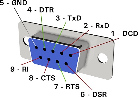
Edision points out the RS232 port. But no further information. No links to the flash utility and worse yet. No pinout for the jack to make a serial connection.
After first installing OpenATV a few years ago the boot screen. Not splash. Changed to OpenATV for every slot I booted from.
I found the flash file to restore the factory Edision boot screen. Sent it to a USB stick. Inserted it and booted the receiver.
It took only a few seconds and the Edision boot screen restored.
Yesterday after wanting to get the oem screen back. OpenATV was installed some time ago in a slot and it took over the boot screen again.
Example. Boot the receiver and see OpenATV and then Openvix splash.
I made a USB with the same file I used before.
It only took a few seconds as it did before. But the receiver froze at 50% for over 5 minutes.
I pulled power. Pulled the USB. And plugged it back in.
No response. No display. No boot. The IR extender and my dish mover display will light up like something is going on.
The Ethernet right amber LED lights up solid for a few seconds. Then goes out. The receiver is not booting.
No putty access, no FTP. No IP address found. It was a static IP. No DHCP.
It's dead.
Power supply checked. Voltage at 12.22 VDC. It will supply current to power a #194 automotive lamp. Currently detached from HDMI, Ethernet, Coax. Nothing but a box.
Will not boot.
That info is to keep 'did you try this and that' to a minimum. I did. Tried an image with noforce renamed to force.
So. Because I am familiar with router and HDD firmware flashing. I hope someone could assist with a serial flash tool that would work and a guide to do it.
I have the Os Mio4k bootloader file. No issues building a serial cable for the 1/8" jack.
But no pinout for the wiring of it.
Please. Could somebody assist me?


